Projects
2025
 The project this year is a shack clock. Everyone needs a clock in the shack, even if it’s only to tell you that you have been playing radio for too long.
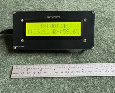
However, this clock is a bit different. It is GPS locked and has a built-in sensor for interior climatic measurements.
The build is based on two PCB’s with a jumbo LCD display.
The picture shows the general layout with the GPS antenna visible
As you would expect the electronics is based round Chinese sourced modules.
The display is just a very large version of the standard 16X2 LCD display
The main module is a GPS receiver with an antenna. This is a UBLOX 6, which communicates via a serial interface.
The climatic module is based on a Bosch sensor. It uses I2C to communicate and can supply temperature, atmospheric pressure, and relative humidity.
The CPU is the standard Atmel 328. This has just enough computing power and speed to do the job, (but only just).
Basic Mode
The basic screen shows time and date, with day of the week. The display is in GMT and updates every second
Climatic Mode
This mode uses data from the Bosch sensor to give information on the conditions in the shack. There are several screens that cycle through in this mode
detailing Air Pressure, Relative Humidity, and Co2 level.
Location Mode
The location mode uses the GPS module to supply data about the location of the clock. This is only really useful if the clock is moved to a new location, eg a portable location. There are screens that give Latitude and Longitude, and ASL Altitude as returned by the GPS signal
The Location option also gives a screen that tells you how many satellites are currently being used to give the fix. The GPS system is sensitive enough to receive many satellites even indoors with just a view of a window.
2024 - Power and VSR Meter
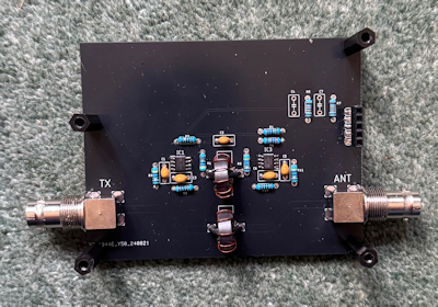
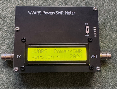 The meter is based on a long existing design that uses a pair of balanced toroid transformers to produce a broadband directional coupler which allows the forward and reverse traveling RF power to be separated.
G8JFX has taken the design a couple of steps further on by using a couple of AD8307 logarithmic power detectors to separately measure the forward and reverse power. This allows real time derivation of the Return Loss and SWR in addition to Forward and Reverse power.
To allow the AD8307’s to operate in their optimum power range an additional 30dB attenuator is included in each of the signal paths. The DC outputs from the AD8307’s are then fed to analog inputs on the processor.
Calculations and Characteristics
So, what does the unit calculate?
The only inputs available to the internal micro processor are the Forward travelling and Reverse travelling power. The first thing it does is to subtract the reverse travelling power from the forward travelling (in dB) to give the return loss of the load.
Return loss is a simple concept that is not used much in the Amateur world but is very popular in the RF professional world. Put simply, it is a measure of how much power is returned to a system from a load.
Now there is obviously a link between VSWR and Return loss and the formula for deriving this is built into the code.
 Operation
The operation is simple. Just connect the input of the bridge to the TX output and connect the antenna to the output. The connections are marked on the top PCB.
No harm will come to the bridge if the connections are reversed. The only issue would be that the Forward and Reverse power measurements will be swapped over
The main program runs in a loop, so it goes on forever. The only way out is to cycle the power.
The four parameters are clear: -
F Forward power in W. Range 0.1W to 99.9W
R Reverse power in W. Range 0.1W to 99.9W
RLS Return Loss in dB. Range 0 to 99dB (1dB resolution)
SWR VSWR as a number. Range 1.00 to 9.99
Battery and Charging
The bridge runs from a single 18650 Lithium-Ion cell. The voltage range for these is 4.2V to 3.0V. I have mentioned that I expect the LCD to function better with above 4.0V supply.
To charge the cell a Chinese PCB is soldered to the top PCB. This includes a TC4056A IC to manage the cell. To charge the cell connect a USB supply via a USB mini plug.
2023 - Dummy Load
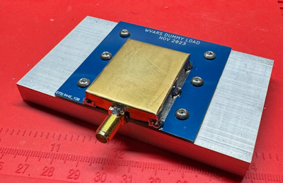 The 2023 project was something a bit different. Rather than a complex bit of electronics it was more of a mechanical challenge. Specifically, a 50ohm dummy load.
This was made from a 150W planar resistor mounted on a small pcb.
The whole thing mounted on a heat sink to dissipate the power.
- (1) Solder the SMA to the pcb
- (2) Mount the pcb to the heatsink
- (3) Mount the resistor to the heatsink
- (4) Solder the resistor to the pcb
- (5) Make the shield box and solder to the pcb
The finished build was useful load that was good to 2Ghz and 10W continuous and more for short periods.
It’s easy to buy adapters from sma to just about any rf connector on eBay.
Another design by Tim G8JFX
2022 - WSPR Beacon
![]() The WARVS project for 2022, was a WSPR transmitter that worked with the previous years Signal Generator.
The WARVS project for 2022, was a WSPR transmitter that worked with the previous years Signal Generator.
WSPR, which stands for Weak Signal Propagation Reporter, is a program used to test the propagation paths
of RF signals between amateur radio operators using a narrowband digital transmission protocol called MEPT_JT
on the HF and MF frequency bands.

